Trace: • GP-Simulator Operation Manual
This is an old revision of the document!
Table of Contents
GP-Simulator Operation Manual
GUI Description
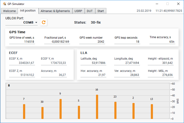
Init Position Tab
In the “Init position” tab, you can configure the connection to the UBLOX receiver for getting the current coordinates, accuracy, as well as time, and information about the satellites being observed.
Almanac and Ephemeris Folder
Once the current time is determined, you can download the Ephemeris and Almanac files.
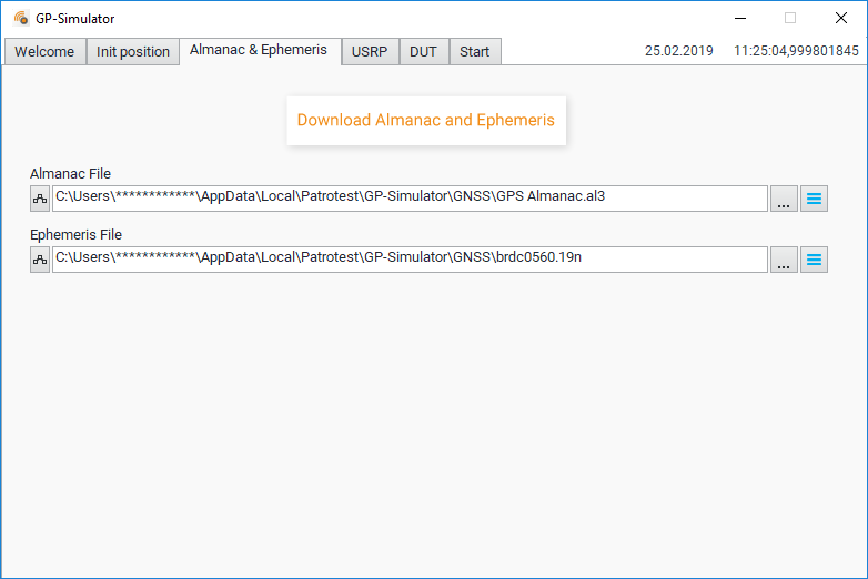
You need internet connection to download the corresponding files.
You can preload the Ephemeris and Almanac files on your computer and then define the path to the files in the corresponding fields.
USRP Tab
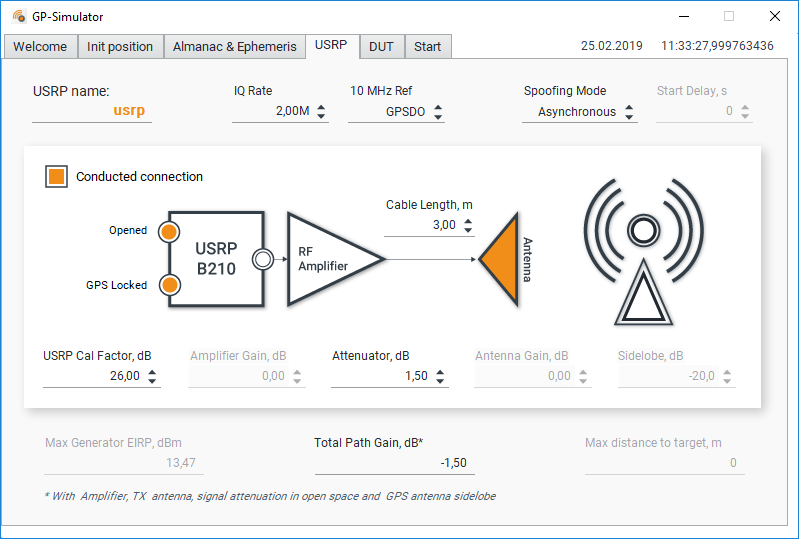
- USRP name - the name of your USPR board, what you already setted in NI-USRP Configuration Utility
- IQ Rate - IQ sample rate. The minimal value is 1.5 MHz. The maximal value is 5 MHz. The higher the value you put, the more CPU of your computer will be loaded.
- 10 MHz Ref - The source of 10 MHz reference frequency: External or GPSDO. In case you work with antenna, GPSDO on your USRP board will be spoofed, so you need to use external high quality reference source.
- Spoofing mode - Asynchronous, Synchronous. Read our article about different types of spoofing.
- Start delay, s - Generation start offset for synchronous mode. Can be used to study the required accuracy of signal synchronization.
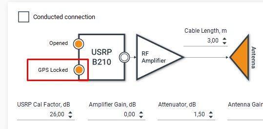
- Conducted connection flag - set it in case you use cable connection to the DUT. In case you work on antenna unset it.
- Opened flag - in case of successful USRP initialization.
- GPS locked flag - in case of successful USRP GPSDO 3D-fix. Synchronous generation available only if this flag is setted.
- Cable Length, m - The total length of all applied cables. It is used for Total Path Gain calculation.
- USRP Cal Factor, dB - USRP calibration value. Calibration procedure described there - USRP Calibration Procedure
- Amplifier Gain, dB - set the gain of the external RF power amplifier in case radiated test.
- Attenuator, dB - total path attenuation in cables and\or attenuators
- Antenna Gain, dB - set the antenna gain in case radiated test.
- Sidelobe, dB - Sidelobe of the receiving antenna of the DUT, taking into account the angle of arrival of the signal. Used to calculate the signal power of the simulator in the phase center of the DUT antenna.
- Max Generator EIRP, dBm - Maximum available Effective Isotropic Radiated Power of the generator with particular amplifier, antenna and cables.
- Total Path Gain, dB - calculated taking into account the antenna gain, power amplifier, attenuation in cables and sidelobe of the receiver antenna
- Max distance to target - Maximum available distance to the DUT.
DUT Folder
Here you can set the distance and direction to the sample in case of field testing:
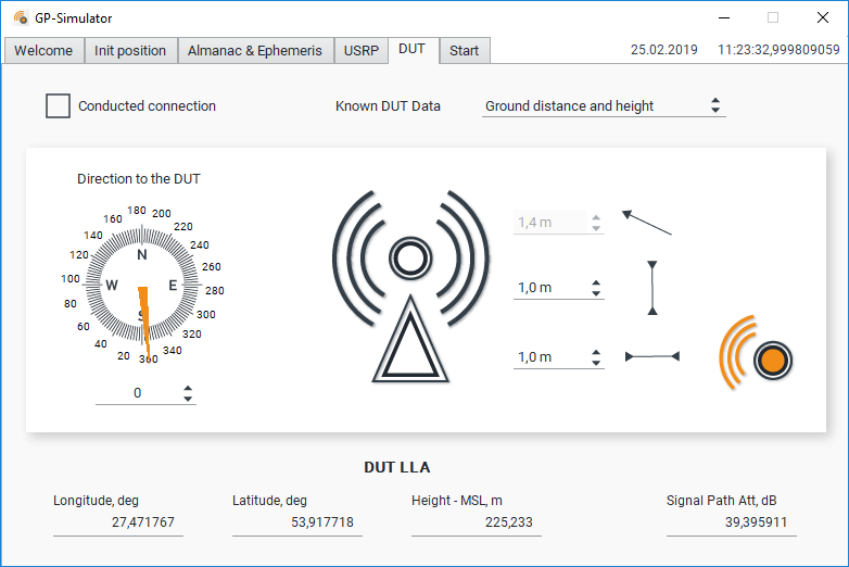
The user can determine the distance to the sample using two methods:
- The distance to the DUT on the ground and the height of the DUT
- The distance to get on the ground and in line of sight.
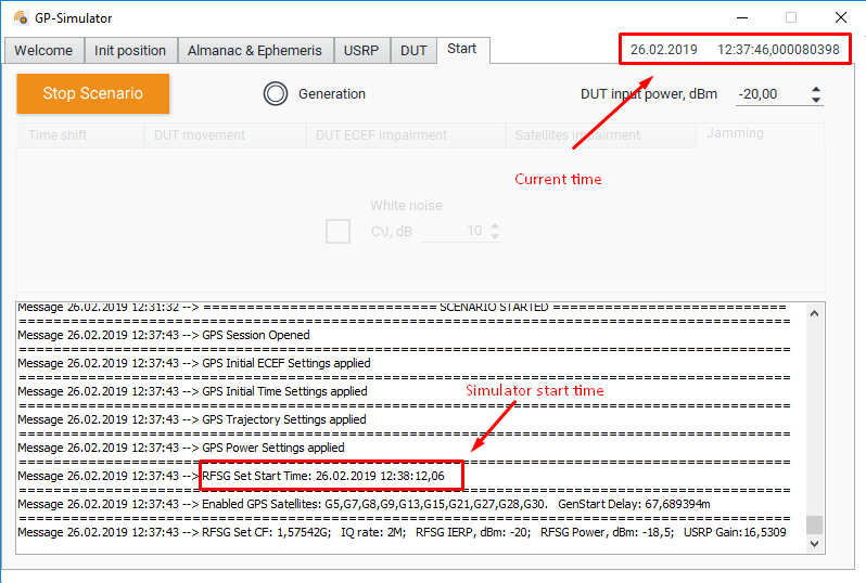
Start Folder
In this tab, the user can start the generation and also distort the signal.
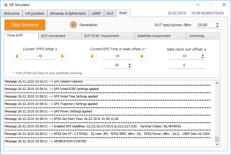
Time shift
Here you can shift the 1PPS or timestamp of the DUT in different ways.
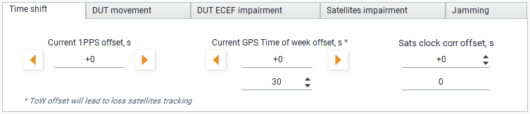
- Current 1PPS offset, s - Adds an offset to the generated sequence in such a way as to shift the 1PPS signal of the DUT.
- Current GPS Time of week offset, s - Dramatically changes the ToW in HOW in all subframes. The position of all satellites is recalculated based on the new time. Thus, the receiver is temporarily lost tracking the satellites. Make sure that the power level of the generated signal is sufficient to block the real signals.
- Sats clock corr offset, s - Sinhronius simulates clock drift on all satellites. Leads to a smooth drift of 1PPS impulse of the DUT
DUT movement
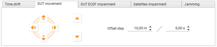
Here you can move the coordinates of the DUT for a certain number of meters for a certain time
DUT ECEF impairment
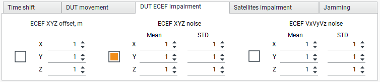
This is the experimental tab. Where can you add an fixed offset and noise to the coordinates of the DUT and the noise to Doppler offset. You can set the mean value and the standard deviation of the noise.
Satellites impairment
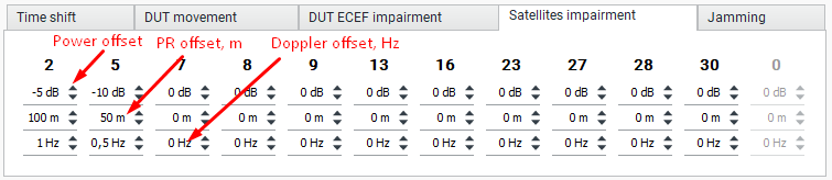
On this tab you can set the relative power, pseudorange offset and Doppler offset for each satellite.
Conducted testing
Below is a typical DUT testing diagram for valuentabilities to spoofing and jamming:
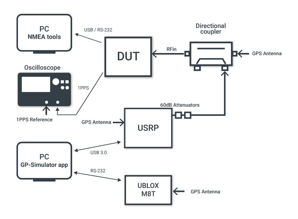
We recommend using a directional coupler to suspend the signal from the simulator to the real signal. Oscilloscope is used for measurement of 1PPS impulse offset.
Application settings
Wait for the UBLOX M8T status to become 3D Fix. Download almanac and ephemeris files. On USRP folder set:
- 10 MHz Ref to GPSDO
- check Conducted Connection
- Set Attenuator value based on cables, attenuators and directional coupler.
On Start folder setup
- DUT input power. Usualy it is within -100 dBm
- Push Start button
Radiated testing
Attention. The use of radiated radio signals may be illegal in your country. Please familiarize yourself with your legislation on the regulation of the radio spectrum before using this app. We are not responsible for your actions.
Below is a typical scheme of using our equipment for field testing of devices for exposure to GPS spoofing:
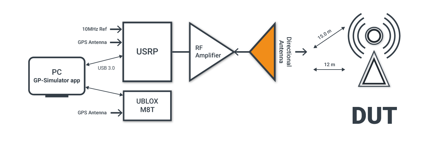
In case of radiated testing you cann't use internal USRP GPSDO like 10 MHz reference source, because it will be spoofed. You have to use external high quality reference source. Frequency stability should be better than 25 ppb.
Application settings
Wait for the UBLOX M8T status to become 3D Fix. Download almanac and ephemeris files. On USRP folder set:
- 10 MHz Ref to External
- uncheck Conducted Connection
- Set Amplifier Gain, Attenuator, Anteanna Gain according to your connected equipment.
On DUT folder setup:
- direction to the DUT
- and known distances
On Start folder setup
- DUT input power. Usualy it is within -100 dBm
- Push Start button
Synchronous and asynchronous mode
In the case of an asynchronous attack, a spoofer transmits false signals that are stronger than the original ones, causing the receiver to lose track of the satellites and lock on to the overpowering spoofing signal(s). On the other hand, synchronous attacks imply transmitting signals that are synchronized with the original ones and then gradually overpowering the latter.
In more detail, the differences are synchronous and asynchronous attack you can read in our article.
In synchronous mode, our simulator generates a signal that is aligned with real up to 100 ns.
The selection of the spoofing mode can be made in the USRP tab:
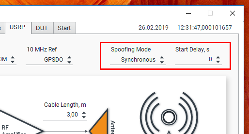
If you selected the synchronous mode, then you can set an additional offset for the start of generation. This is convenient for examining the DUT correlation analysis window.
To work in synchronous mode, you must wait for the flag: “GPS Locked”:
In synchronous mode, the generation does not start immediately, but only at a certain time: